Clothes Dryer Troubleshooting
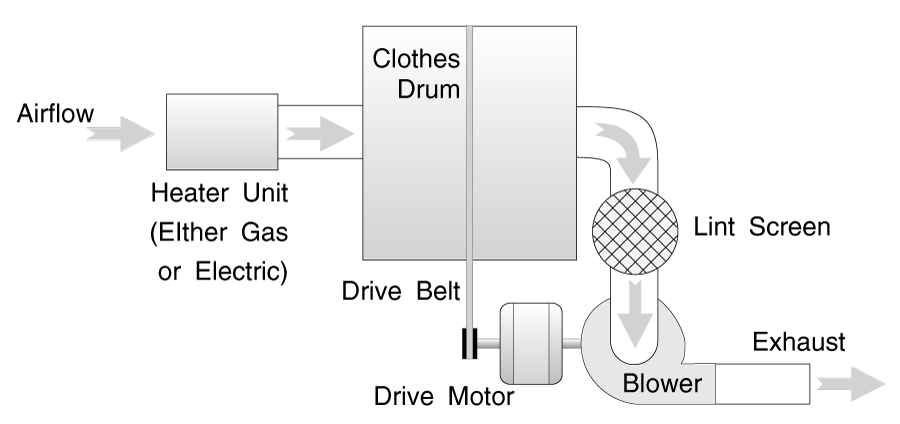
The main idea of a dryer is to circulate warm air through wet clothes to evaporate moisture from them. This sounds really simple, but there are many implications. This means that all dryers have to have a blower to move air and a heat source to warm the air, and that airflow is very important. It also means that all dryers must have a way to toss the clothes around a bit, because air won't circulate through them if they're just laying there in a big wet lump. This is done, of course, by "tumbling" them in a big round drum.
The main differences between different makes and models are the way the drum is supported, the layout of any electric heaters, and airflow.
All dryers have a drive motor which turns the drum through a belt. In most dryers, the motor also turns a blower fan connected directly to the motor shaft; in a few notable exceptions, the fan is belted off the drive motor, too.
Warm air evaporates moisture much faster than cold air, so all dryers also have a heat source. The heat source in household machines is either gas or electric. Electric heating elements come in many different configurations; see the chapter about your brand for details.
Gas burners are remarkably similar in all the different brands. Ignitor systems and holding coils on the gas safety valves have varied slightly over the years, but you can find the diagnosis and repair procedures for all gas burners covered by this manual in section 2-3.
A temperature control system keeps the air at the optimum temperature for drying and prevents scorching of your clothes. This system uses several thermostats; some adjustable and others a fixed temperature. Testing the temperature control system is discussed in section 2-4(c). Finding the thermostats is discussed in the chapter pertaining to your model.
There is also a safety system that prevents the heating system from starting at all unless the blower is turning. This prevents overheating of the system or natural gas buildup in the dryer cabinet. A contact in the centrifugal motor starting switch assembly only allows the heating system to heat if the motor is running.
Airflow is EXTREMELY important in removing the moisture from the dryer drum; thus the blower, vents and exhaust ducting must be kept as clean (translation: free of lint) as possible. This also prevents overheating of electric heating elements and accidental lint fires, and insures enough airflow to keep the gas burner operating properly.
Also, drum seals can wear out and leak, which can disrupt proper airflow.
The lint screen traps most lint, but some does get through or leak out around the drum seals. Over a period of years, enough can build up enough to allow some of the above symptoms to occur. The airflow system is discussed in section 2-5, except for drum seals, which are discussed in the chapter pertaining to your brand of dryer.
In most models, the blower is the last component in the airflow system. (See Figure G-1) From the blower, the air goes directly out the dryer exhaust. Thus, the other components are not under pressure. Air is being sucked through them, so they are under a vacuum.
Some dryer timers are simply devices that run the motor for a set number of minutes; others integrate temperature control and even moisture (humidity) controls. Yet others are solid-state, electronic units. If you have a separate timer and temperature control, consider yourself lucky; the combined units are considerably more difficult to diagnose and generally more expensive to replace. Diagnosis is discussed in Chapter 2-4(b).
Dryers are relatively simple machines; they just don't have many components. So most repairs stem from just a few common complaints:
1) NOT DRYING WELL
(See also NO HEAT below)
Usually this is caused by poor airflow. Feel the dryer vent exhaust (usually outside the house.) If there isn't a strong blast of air coming out, check the lint screen and open up any dryer vent you can get to to check for clogging. Also check any flexible dryer vent for pinching.
In some machines, if the drum is not turning, there will be no noise or other external symptoms. The clothes will simply be laying there in a big wet lump and they won't dry. The dryer probably won't sound normal either. To diagnose, start the machine empty, open the door and look inside quickly, or depress the door switch to see if the drum is turning. If not, the belt or belt tensioner may be broken. To repair, see the chapter about your brand.
You may see similar symptoms if the motor has gone bad, except that you probably will not hear the motor turning. If the motor is locked, you may hear it buzzing. See section 2-4(d) about motors.
2) NO HEAT, OR LOW HEAT
This can be caused by poor airflow in all dryers, but especially in gas dryers. Check the dryer vent and exhaust as described in NOT DRYING WELL above.
This can also be caused by a problem with the air heating system within the dryer. See section 2-4(c) about thermostats and temperature control systems, section 2-3(a) about gas burners, or section 2-4(f) and the chapter about your brand for information about electric heating elements.
3) DRUM NOT TURNING
See "NOT DRYING WELL" above.
4) DRUM CONTINUES TURNING WITH DOOR OPEN
Most likely the door switch needs replacement. See the chapter on your machine to open the cabinet to get to the door switch.
5) TOO HOT
This complaint is sometimes caused by thermostat problems, (see section 2-4(c). but in an electric dryer, it may be caused by poor airflow. See sections 2-1(b) & (c). Check the dryer vent and exhaust as described in NOT DRYING WELL above.
6) NOISY OPERATION
A vast majority of these complaints stem from drum supports that have worn out. It usually sounds like a loud, low-pitched rumbling sound that slowly gets worse over a period of several months or even years. This is a very common complaint in Whirlpool or Kenmore brand dryers about 7 to 15 years old. See the chapter about your brand for specifics about replacing the drum support rollers.
In some models, notably GE, if a belt breaks, the belt tensioner will touch the drive motor shaft and a loud grinding or clattering noise will result. Replace the belt as described in the chapter about your brand.
You may get a rumbling noise if a belt tensioner pulley seizes up or the tensioner spring breaks.
A regular clack-clack sound as the dryer drum is turning may be coins stuck inside the removable plastic dryer vanes. This can happen in Whirlpool or Kenmore dryers, as well as some other brands, though it is infrequent. To solve the problem, open the top of ther dryer as described in the Whirlpool section, then remove the plastic vane on the inside of the dryer drum by removing the screws on the outside of the dryer drum that hold it in place.
In some models, notably Maytag and Frigidaire machines, things can get by the lint screen (like pencils and pens) and get stuck in the blower wheel. Again, it's a loud grinding sound, as if you were sticking something into a moving blower fan. See the section about your brand for details about how to get to the blower in your machine.
To access the burner assembly, open the gas burner inspection door. Unless specified otherwise in the section about your dryer brand, this door is found on the lower left or right front of the dryer cabinet.
Gas burners can generally be divided into two broad categories; pilot and pilotless ignition. Pilot ignition models have not been manufactured in a number of years, and thus tend to be older units, but there are still a significant number of them in operation.
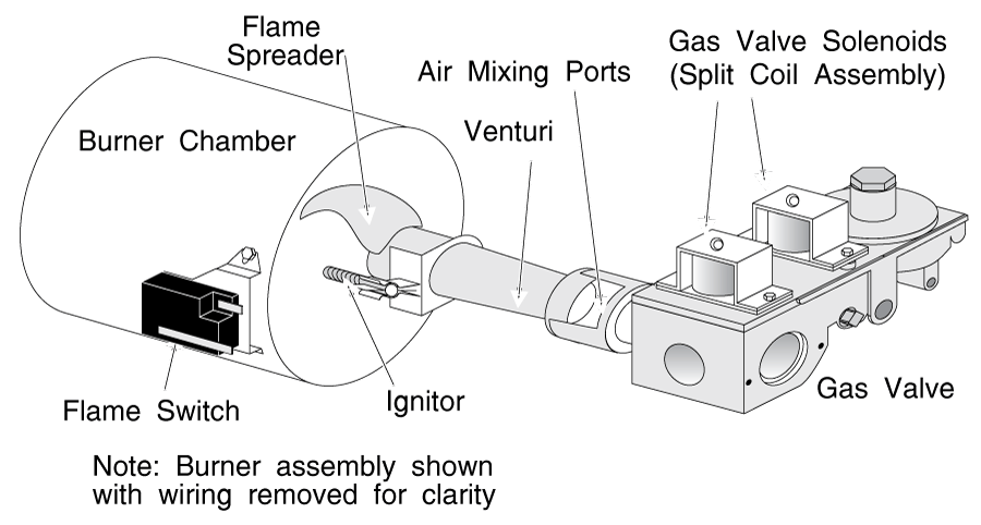
The main components of the system (see Figure G-2 and G-2a) are the gas valve, venturi and burner chamber, and gas safety solenoids (in all models,) the flame sensor and the ignitor (in pilotless models,) or the pilot orifice and sensor (in pilot models.)
IGNITORS
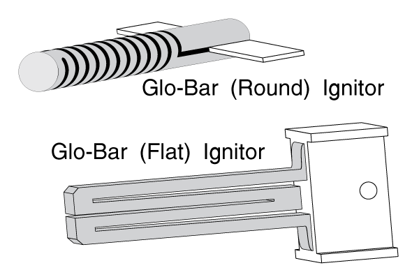
Most ignitors just glow until the burner mechanism opens the gas valve.
See figure G-3 for pictures of the different types of ignitors.
NORMAL BURNER OPERATION
A normally operating gas burner system will have a clean, mostly blue flame (perhaps occasionally streaked with just a little tinge of orange) that cycles on and off every couple of minutes.
When the flame is off and starts to cycle on, you will hear a loud click. In a pilot system, the gas valve will open and the flame will kick on at this time. In a pilotless system, the ignitor will heat up and glow brightly for about 7-15 seconds. The flame sensor senses the heat from the ignitor. If it is glowing, you will hear another click, the gas valve will open and the flame will kick on. This is a safety feature; if you don't have ignition, you certainly don't want to open the gas valve and dump gas into the dryer cabinet.
When the air in the dryer drum reaches the chosen temperature (as sensed by the thermostats) the gas valve will close and the flame will shut off.
IGNITOR DOESN'T GLOW (PILOTLESS SYSTEMS ONLY)
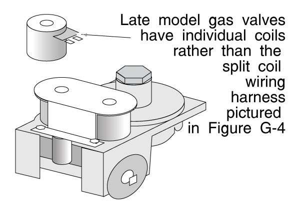
Nine times out of ten, if the ignitor is not glowing, it is burnt out. Unplug the dryer and remove the burner assembly as shown in figure G-4. Usually you will see a white or yellowish burned area and a break in the ignitor. If so, replace the ignitor. If you can't see an obvious break, test the ignitor for continuity as described in section 2-4(e).
If the ignitor is not defective, you need to isolate whether the problem is in the control (thermostat) area, or at the burner itself.
The general idea is that if you have 110 volts getting to the burner assembly, then the thermostats are OK, and something in the burner assembly is bad. If you don't have 110 volts at the burner, then a thermostat or some other control is bad.
Perform the following test:
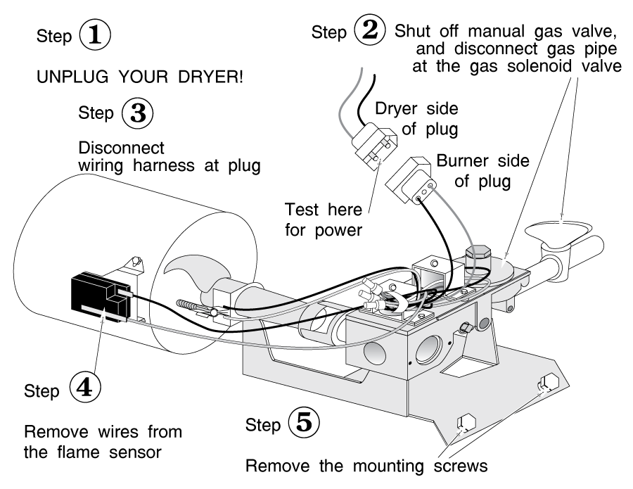
1) Unplug the dryer and open the burner inspection cover as described in the chapter about your brand.
2) Unplug the main wiring harness leading to the burner assembly. (Figure G-4)
3) Using your alligator jumpers, connect a VOM to the dryer side of the harness plug. (as opposed to the side of the harness plug that's connected to the burner.)
4) Make sure no wires will get caught up in the turning drum. Set your dryer timer to the "on" position, high heat, and plug in the dryer. If your VOM reads 110 volts, something in the burner assembly is bad. If the burner isn't getting voltage, the problem is in one of the components of the heating control system: a thermostat, timer or temperature control switch, or motor centrifugal switch.
If you trace it to the burner assembly, and you've already eliminated the ignitor as the problem, either the flame sensor or the gas valve solenoid coil(s) are bad. Unplug the dryer, disconnect the flame sensor and test it for continuity. If you have no continuity, the flame sensor is bad. If you have continuity, the coils are bad. Bring the burner assembly to your parts dealer to make sure you get the right coil assembly, and don't forget to bring the model number of the machine.
IGNITOR GLOWS, BUT FLAME DOES NOT START (GAS VALVE DOES NOT OPEN)
(PILOTLESS SYSTEMS ONLY)
Either the flame sensor is not working properly or the safety solenoid coils are not opening the gas valve. If the ignitor doesn't stop glowing, the flame sensor is bad. If the ignitor cycles on and off, the gas solenoid coil(s) are bad.
FLAME STARTS (GAS VALVE OPENS)
BUT KICKS OFF QUICKLY (SHORT-CYCLES, LOW HEAT)
Usually this problem can be traced to airflow problems, especially if the flame is very orangey-colored while it is on (rather than blue.) The solution is to clean out your lint screen or dryer exhaust. It is an especially common problem in installations where the dryer exhaust runs a long way before venting to the outside. Repair as described in section 2-5.
This may also be caused by a defective flame sensor. Test as described in the section above, "IGNITOR DOESN'T GLOW"
Occasionally this problem can be caused by a bad thermostat. Test as described in section 2-4(c).
PILOT WON'T STAY LIT (PILOT SYSTEM ONLY)
If the pilot won't stay lit, the pilot & unlatch assembly is usually defective.
The pilot & unlatch assembly (figure G-5) is a safety mechanism. If there is no pilot, it closes off the gas to both the pilot and the main gas valve. This prevents accidental buildup of gas in the dryer cabinet.
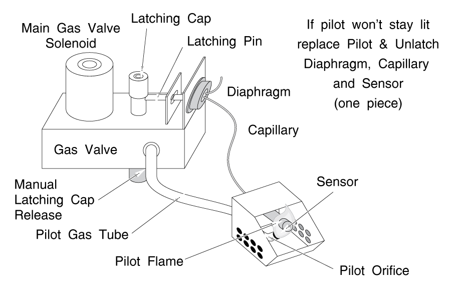
The sensor is simply a bulb, like a thermometer bulb, with a liquid inside that expands when the pilot flame heats it. The liquid pushes against a metal diaphragm that holds the spring-loaded gas valve open. If the pilot goes out, the liquid cools and the diaphragm lets the spring close the gas valve.
In order to light the pilot, you must manually hold the valve open for a minute or so, until the sensor heats up enough to hold the valve open.
PILOT BURNS, BUT FLAME DOES NOT START (PILOT SYSTEM ONLY)
The gas valve solenoid coil is not opening the main gas valve. Either the gas valve solenoid coil is defective, or the burner is not getting the signal to start burning from the heating control system.
Test the wiring as described previously in the "IGNITOR DOESN'T GLOW" section to see if it is getting the 110-volt signal from the heating control system.
If so, the gas solenoid valve is bad. Replace it.
If the burner isn't getting 110 volts, something is wrong with the heating control system as described previously in the "IGNITOR DOESN'T GLOW" section.
Before you start, I want to impress upon you something really important. In electric dryers, you're usually dealing with 220 volt circuits. DO NOT TAKE THIS LIGHTLY. I've been hit with 110 volts now and then. Anyone who works with electrical equipment has at one time or another. It's unpleasant, but unless exposure is more than a second or so, the only harm it usually does is to tick you off pretty good. However, 220 VOLTS CAN KNOCK YOU OFF YOUR FEET. IT CAN DO YOUR BODY SOME SERIOUS DAMAGE, VERY QUICKLY. DO NOT TEST LIVE 220 VOLT CIRCUITS. If you have a heart condition, epilepsy, or other potentially serious health conditions, well...hey, it's just my opinion, but you shouldn't be testing 220 volt circuits at all. It's not worth dying for.
Sometimes you need to read a wiring diagram, to make sure you are not forgetting to check something. Sometimes you just need to find out what color wire to look for to test a component. It is ESPECIALLY important in diagnosing a bad timer.
If you already know how to read a wiring diagram, you can skip this section. If you're one of those folks who's a bit timid around electricity, all I can say is read on, and don't be too nervous. It will come to you. You learned how to use a VOM in Chapter 1, right?
Each component should be labelled clearly on your diagram. Look at figure G-6. The symbols used to represent each component are pretty universal; for example, two different symbols for thermostats are shown, but both have a little square line in them, so you know they're thermostats.
A few notes about reading a wiring diagram:
Notice that in some parts of the diagram, the lines are thicker than in other parts. The wiring and switches that are shown as thick lines are inside of the timer.
Also note that since heaters and ignitors are both a type of resistor, they may be shown with the resistor symbol (a zig-zag line) or they may have their own square symbol, but they should be clearly marked.
The small circles all over the diagram are terminals. These are places where you can disconnect the wire from the component for testing purposes.
If you see dotted or shaded lines around a group of wires, this is a switch assembly; for example, a temperature or cycle switch assembly. It may also be the timer, but whatever it is, it should be clearly marked on the diagram. Any wiring enclosed by a shaded or dotted box is internal to a switch assembly and must be tested as described in sections 2-4(a) and 2-4(b).
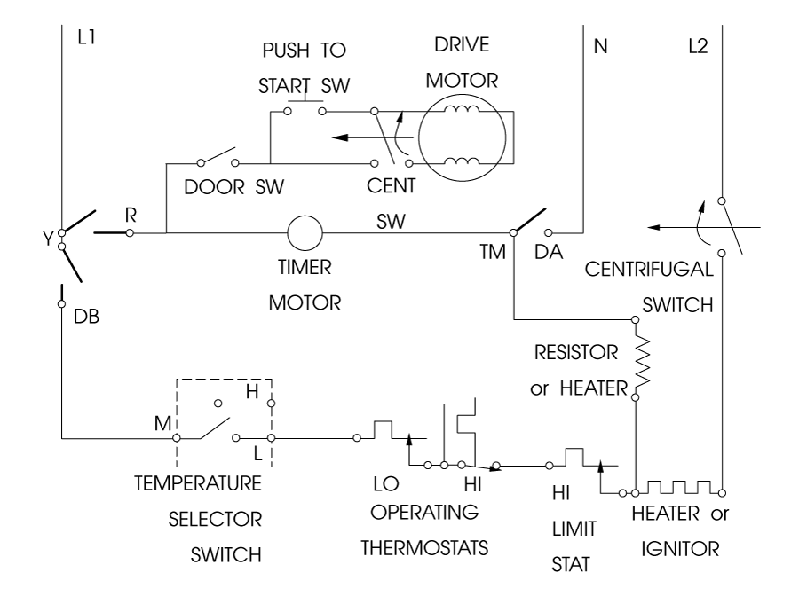
Switches may be numbered or lettered. Those markings can often be found cast or stamped into the switch. To test a switch with a certain marking, mark and disconnect all the wires from your timer. Connect your ohmmeter to the two terminal leads of the switch you want to test. For example, in figure G-6, if you want to test the hi-temp selector switch, connect one lead to the M and one to the H terminal. Then flick the switch back and forth. It should close and open. If it does, you know that contact inside the switch is good.
Remember that for something to be energized, it must make a complete electrical circuit. You must be able to trace the path that the electricity will take, FROM the wall outlet back TO the wall outlet. This includes not only the component that you suspect, but all switches leading to it.
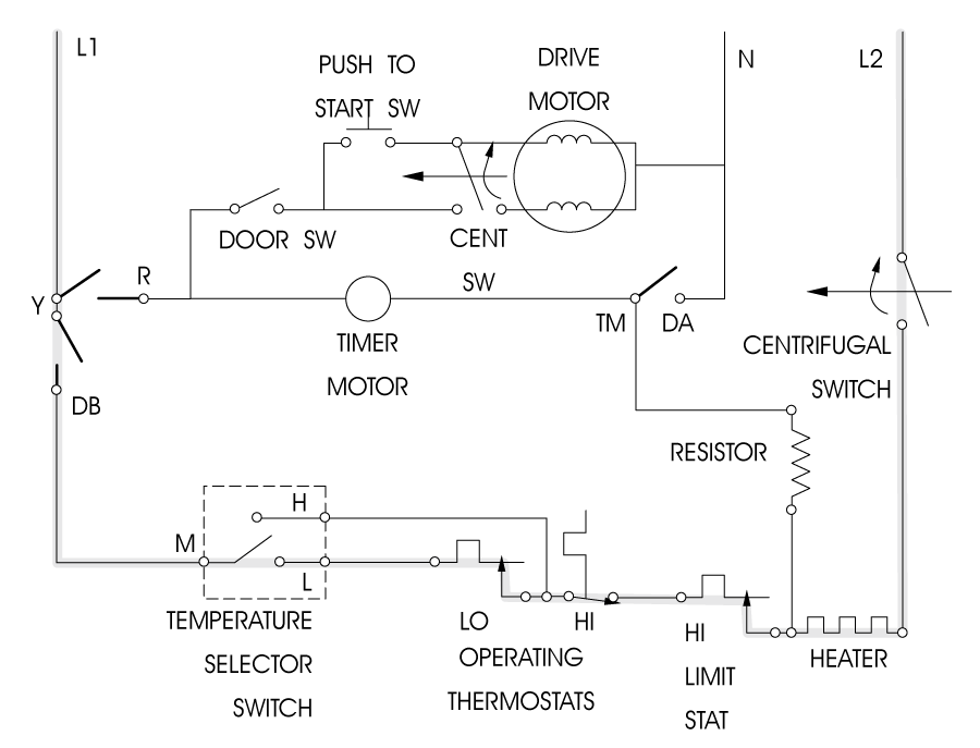
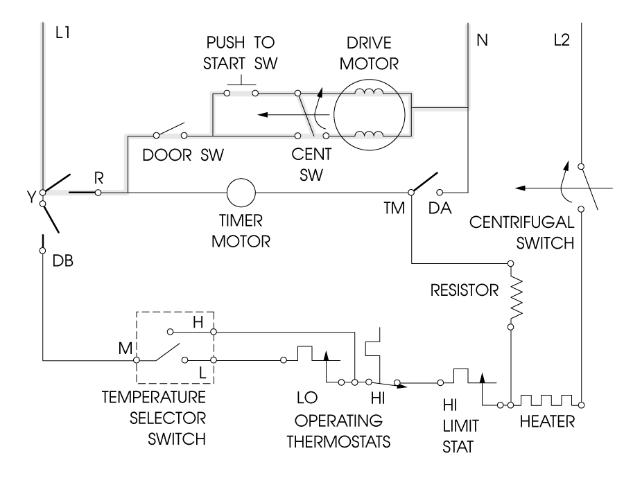
In Figure G-6(a), which shows a typical electric dryer, L1, L2, and N are the main power leads; they go directly to your wall plug. Between L1 and N, you will see 110 volts. Between L2 and N, you will also see 110 volts. But between L1 and L2, you will see 220 volts.
In gas dryers, L1 and L2 will be 110-volt leads. Sometimes they will be labelled L1 and N, but they are still 110 volt leads.
Let's say you need to check out why the heater is not working. Since a burnt out heater element is the most likely cause of this symptom, first test the heater for continuity. If you have good continuity, something else in the circuit that feeds the heater must be defective.
Following the gray-shaded circuit in figure G-6(a), note that the electricity flows from L1 to L2, so this is a 220-volt circuit.
From L1 the electricity flows to the Y-DB switch. This switch is located inside of the timer (you know this because it is drawn with thick lines) and it must be closed. The power then goes through the wire to the temperature selector switch. In this example, we have set the temperature on "low." Note that in this machine, on this setting, the electricity flows through both the high-temp and low-temp operating thermostats. Therefore, both thermostats must be closed and show good continuity. The electricity then flows through the high limit thermostat, so it too must be closed and show good continuity.
The electricity flows through the heater, which we have already tested and we know is good. Then the electricity flows through the centrifugal switch, which must be closed, before going back out the main power cord (L2).
To test for the break in the circuit, simply isolate each part of the system (remove the wires from the terminals) and test for continuity. For example, to test the thermostats in our example, pull the wires off each thermostat and test continuity across the thermostat terminals as described in section 2-4(c).
The Y-DB switch is shown in bold lines, so it is inside the timer. For now, let's ignore this switch. (Remember; the timer is the last thing you should check; see section 2-4(b).)
That leaves the centrifugal switch, which is only closed when the motor is running. However, if you can identify the proper leads, you can use your alligator jumpers to jump across them. If you do this and the heater kicks on when you turn on the timer, you know the switch is bad.
If NONE of the other components appear to be defective, test the timer as described in section 2-4(b).
To check for a wire break, you would pull each end of a wire off the component and test for continuity through the wire. You may need to use jumpers to extend or even bypass the wire; for example, if one end of the wire is in the control console and the other end in underneath the machine. If there is no continuity, there is a break in the wire! It will then be up to you to figure out exactly where that break is; there is no magic way. If you have a broken wire, look along the length of the wire for pinching or chafing. If there is a place where the wires move , check there first. Even if the insulation is O.K., the wire may be broken inside.
Testing switches and solenoids is pretty straightforward. Take all wires off the component and test resistance across it.
Switches should show good continuity when closed and no continuity when open.
Solenoids should show SOME resistance, but continuity should be good. If a solenoid shows no continuity, there's a break somewhere in the windings. If it shows no resistance, it's shorted.
The timer is the brain of the dryer. It controls everything in the cycle. In addition to telling the motor when to run, it may also activate the heating circuit or heating control circuits, humidity-sensing circuits, etc.
Solid state timers are difficult and expensive to diagnose. If you suspect a timer problem in a solid-state system, you can try replacing it, but remember that it's expensive and non-returnable (being an electrical part.) If you have one of these units that's defective, you can check into the cost of replacing it, but it's been my experience that you usually will end up just replacing the whole dryer or calling a technician. If you do call a technician, make sure you ask up front whether they work on solid-state controls.
Most timers are nothing more than a motor that drives a set of cams which open and close switches. Yet it is one of the most expensive parts in your dryer, so don't be too quick to diagnose it as the problem. Usually the FIRST thing a layman looks at is the timer; it should be the LAST. And don't forget that timers are electrical parts, which are usually non-returnable. If you buy one, and it turns out not to be the problem, you've just wasted the money.
In a wiring diagram, the wiring and switches that are inside the timer will usually be drawn with dark lines.
TIMER DIAGNOSIS
If the timer is not advancing only in the automatic or humidity control cycle, (i.e. more dry-less dry on your timer dial) see section 2-4(c) about 3-lead thermostats.
If the timer is not advancing in all cycles, well, that's pretty obvious. Replace the timer or timer drive motor, or have it rebuilt as described below.
Timers can be difficult to diagnose. The easiest way is to go through everything else in the malfunctioning system. If none of the other components are bad, then it may be the timer.
Remember that a timer is simply a set of on-off switches. The switches are turned off and on by a cam, which is driven by the timer motor. Timer wires are color-coded or number-coded.
Let's say you've got a motor starting problem. Following the shaded circuit in figure G-7, you test the door switch, push-to-start switch and centrifugal switch. They all test ok. So you think you've traced the problem to your timer.
First unplug the machine. Looking at your wiring diagram, you see that the Y-R switch feeds the drive motor. REMOVE those wires from the timer and touch the test leads to those terminals. Make sure the timer is in the "on" position and slowly turn the timer all the way through a full cycle. (On some timers, you cannot turn the dial while it is on. You must simply test the timer one click at a time. Be patient!)
You should see continuity make and break at least once in the cycle; usually several times. If it doesn't, the internal contacts are bad; replace the timer.
In general, timers cannot be rebuilt by the novice. Check with your parts dealer; if it can be rebuilt, he'll get it done for you. If it's a common one, your parts dealer may even have a rebuilt one in stock.
For the most part, if your timer is acting up, you need to replace it. To replace, mark the wires or note the color codes written on the timer. If you need to, you can draw a picture of the terminal arrangement and wire colors. If possible, change over the timer wires one-by-one. It can be easier. If there are any special wiring changes, they will be explained in instructions that come with the new timer.
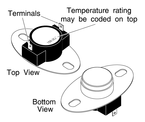
THERMOSTATS (Figure G-8)
A thermostat is basically just a switch that opens or closes according to the temperature that it senses.
This switch can be used to turn the heating system (either gas or electric) on and off to maintain a certain air temperature range at a given place in the system. There may be several different thermostats side by side; for example 135 degrees for low temperature, 165 for high temperature, etc. You choose which thermostat is used by selecting the temperature on the dryer console.
There are exceptions; for example, Frigidaire used a specially-designed thermostat that has five leads instead of two. Naturally, it is a bit more expensive than regular thermostats, and difficult to test.
You can test a thermostat as described in section 1-4(b) by testing for continuity across its terminals. A cold operating stat or hi-limit stat should show continuity. A cold cool-down stat should show no continuity.
If a thermostat fails into a closed position, there is a danger that the heating system will continue operating until something catches fire. To prevent this, there is a high-limit thermostat that will cut out the entire heating system.
There is no way to repair thermostats. Replace any that are bad.If you suspect it's defective, it probably is. Replace it.
THERMISTORS
A thermistor is a "variable resistor" whose resistance varies with temperature. Rather than just turning the heating circuit on and off as thermostats do, dryers with solid-state (computer logic board) controls can use a thermistor's input to control the drum temperature more closely. This can result in lower energy usage.
Thermistors are tested by measuring resistance across them with a VOM. A cold thermistor should show no resistance. Replace if defective.
THERMAL FUSE
This fuse will blow when too high a temperature is sensed at the outlet; usually when one of the operating thermostats has failed.
AUTO CYCLES (More Dry-Less Dry)
In an "auto" cycle, the system has some way of sensing how much moisture is in the air inside the dryer drum. If the air is dry, the timer advances more quickly to end the cycle sooner. This is done in one of two ways.
When the air in the drum is moist, the water in it absorbs heat to evaporate. This keeps the air temperature lower, and it takes longer to heat up.
The thermostat on the drum exhaust will keep the heating system on longer. In these systems, that same thermostat controls the timer motor; while the heating system is on, the timer motor is not running, and vice-versa. So when the clothes get drier, the exhaust air temperature gets higher more quickly, the heating system doesn't stay on for as long and the timer motor runs more, ending the cycle sooner.
The thermostats in these machines have three leads. One side goes to the timer motor, the other to the heating system. These thermostats are also difficult to test without any way to heat them up. But they're pretty cheap. If the symptoms lead you to suspect that yours is defective, just replace it.
Besides heating more slowly, moist air also conducts electricity better than dry air. So another way the engineers design a humidity sensor is to put two electrical contacts inside the dryer drum. The electrical currents conducted by the air are so low that an electronic circuit is needed to sense when the air is moist, but essentially the same thing happens in this system as in the other. When the air is moist, the timer motor doesn't run as often. When the air is dry, the timer motor runs longer and times out sooner.
The sensors in these machines tend to get coated with gummy stuff, especially if you use a lot of fabric softener in the wash or starch in ironing. If the timer is not advancing during the auto cycle, this is likely what has happened. Try scrubbing the sensors with a little kitchen cleaner, such as 409 to get it off. In extreme cases, use a little rubbing alcohol as a solvent. The circuit board could have gone bad, too; there is no good way to test it with out a lot of expensive equipment. If you think it has gone bad, it probably has. Replace it.
SPECIAL NOTE: In electric dryers with an automatic cycle, a special problem exists. The problem is that the heater operates on 220 volts, but the timer motor runs on 110 volts. There is a resistor in the system to cut down the voltage (see figure G-6(a) and if this resistor is bad, you will see the same symptoms as if the thermostat was bad: the timer motor will not run in the automatic cycle. If you have one of these dryers, make sure you test the resistor for continuity, in addition to the thermostat.
OTHER TEMPERATURE CONTROLS
Selecting which thermostat is used may be done inside the timer, or there may be a separate multi-switch that accomplishes this. Test internal timer switches as described in section 2-4(b).
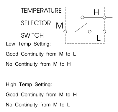
Separate temperature selector switches are tested either by measuring continuity through each contact (figure G-9) or by jumping across the two correct terminals with your alligator jumpers.
A motor that is trying to start, but can't for whatever reason, is using one heckuva lot of electricity. So much, in fact, that if it is allowed to continue being energized in a stalled state, it will start burning wires. To prevent this, an overload switch is installed on motors to cut power to them if they don't start within a certain amount of time.
If the motor is trying to start, but can't, you will hear certain things. First will be a click, followed immediately by a buzzing sound. Then, after about 5 to 20 seconds of buzzing, another click and the buzzing will stop. The sounds will keep repeating every minute or two. In some extreme cases, you may even smell burning.
If you hear the motor doing this, but it won't start, disconnect power and take all the load off it. For example, disconnect the drive belt, and make sure nothing is jamming the blower wheel. The motor should turn easily by hand.
Try to start the motor again. If it still won't start, the motor is bad. If you have an ammeter, the stalled motor will be drawing 10 to 20 amps or more.
STARTING SWITCH
Dryers have a centrifugal starting switch mounted piggyback on the motor. There are many sets of contacts inside the switch, and each design is different, even among dryers of the same brand. Testing the switch is most easily accomplished by replacing it.
Remember that starting switches are electrical parts, which are generally not returnable. If you test the switch by replacing it, and the problem turns out to be the motor itself, you will probably not be able to return the starting switch for a refund. But they're pretty cheap, and if it is the problem, you just saved yourself the best part of a hundred bucks for a new motor.
If the motor is stalled (buzzing and/or tripping out on the overload switch) and the starting switch tests O.K., the motor is bad. Replace it.
NOTE: Many motors have the belt pulley pressed onto the motor shaft. However, a replacement motor may come without a pulley. When buying a new motor, make sure that the pulley can be changed over, or else get a new pulley with the new motor. It may save you a second trip to the parts dealer.
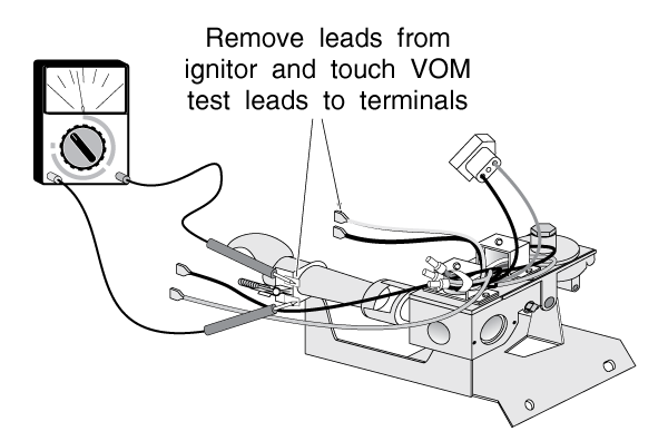
You can test the ignitor by testing for resistance across the element. (See figure G-10) A good ignitor will show quite a bit of resistance, between about 50 and 600 ohms. A bad ignitor will usually show no continuity at all.
Electric heater elements are tested by measuring continuity across them. Like ignitors, they should show quite a bit of resistance, and defective heaters will usually show no continuity at all.
In most electric dryer installations, there is a 220 volt wall plug. If the dryer does not seem to be getting power, but you do have power at the wall outlet, you also need to check the terminal block for problems as shown below. The terminal block is where the main power cord attaches to the dryer's circuitry.
It will be just inside the back somewhere; usually there is a cover or access plate you can remove to get to it. (see figure G-11)
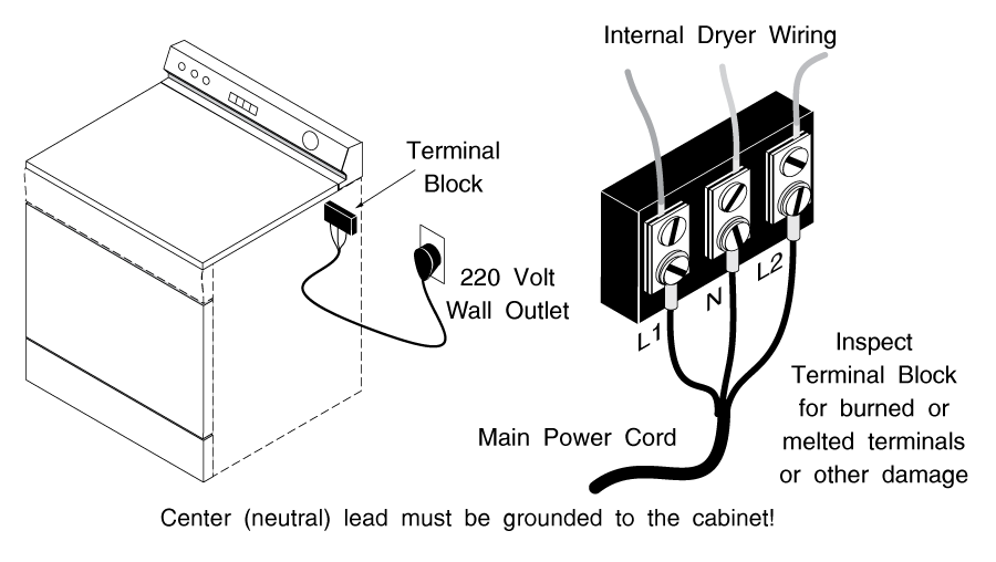
Inspect the terminal block for any signs of damage; overheating, melted terminals or wires, etc. Replace it if there is any sign of problems.
Make sure all wiring is clear and make sure you don't touch any bare wires or terminals, plug the dryer back in briefly, and check the terminal block for power across all three legs as described in sections 1-4(a) and 2-4. Then remove power again at the breaker or fuse.
Airflow is EXTREMELY important in EVERY dryer. Any blockage can cause slow drying or no drying. It can come on suddenly (like if something happens to the dryer vent outside the house) or it can show up as a progressive problem, as lint slowly builds up in the dryer exhaust system.
First, check the lint screen. It seems obvious to you and me, but don't take it for granted. Check the screen yourself, regardless of who else says they've checked it. I ran into one old gentleman who'd been widowed ten months before. His only problem was a clogged lint screen (we're talkin' clogged here; the lint was literally about two inches thick on the screen.) His wife had always done the laundry, and he simply didn't know that he had to clean the screen. I think it's a tribute to Whirlpool engineering that the thing was still running at all with that much lint in it.
If the lint screen is clean, check the exhaust system between the dryer and the house outlet. A really easy way is to disconnect the exhaust system and run the dryer for a few minutes with it venting directly into the house. If the dryer functions normally, the exhaust system is clogged.
If none of the above works, the internal ducting or blower fan is clogged or malfunctioning. To open the dryer and clean out the ducting, see the chapter about your brand.
NOTE: Many clothes dryer models CAN be operated with the front of the cabinet taken off, but since there is nothing enclosing the dryer drum, there will be no airflow, and the heating system will not operate properly. In fact, doing this will overheat the heating system.
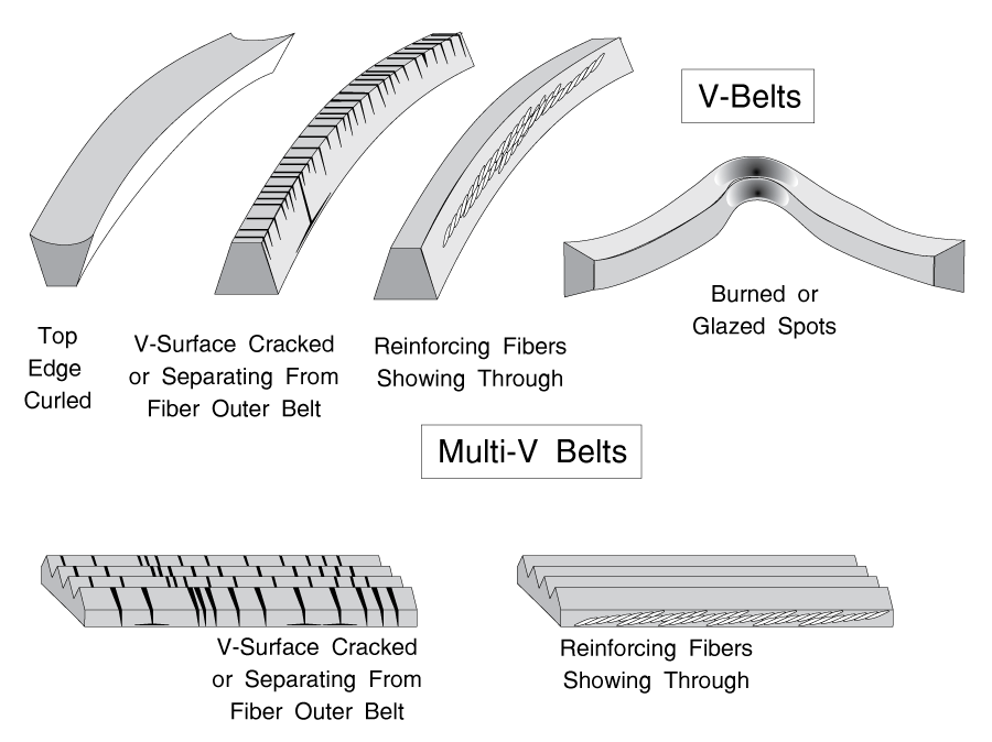
To access the drive belt, see the chapter about your brand.
If you see any of the problems pictured in figure G-12, replace the belt.
It is important for the belt tensioner to be operating properly. Check for broken springs. Also check that the tensioner idler roller spins freely.
Please share our .