Washing Machine Repair
NOTE: Chapter 2 covers problems common to almost all washer designs.
THIS chapter covers only diagnosis and repairs peculiar to CERTAIN Maytag-designed machines.
If you do not read Chapter 2 thoroughly before you read this chapter,
you probably will not be able to properly diagnose your machine!!!!
The design uses a reversing motor, which is belted to both the pump and the transmission, using two different belts. At times, both one-speed and two-speed motors were used. When viewed from the top, the motor turns clockwise for the agitation cycle, and counterclockwise for the spin cycle. (Figure M-1)
To switch between the two cycles, there is a brake in the hub of the drive pulley, and a clutch in the transmission. During agitation, the brake keeps the transmission casing from turning, and the drive pulley turns the transmission shaft. During the spin cycle, the brake releases and the whole transmission starts slowly spinning around. Since the basket is attached to the transmission casing, it spins, too.

A clutch built into the transmission allows slippage until the basket gets up to speed. At the end of the spin cycle, the motor stops and the brake brings the basket to a stop.
In the late '80's, Maytag redesigned the transmission. The result is the "orbital" transmission, which has just a few moving parts and is serviceable in the machine. One is supposed to be able to replace the other directly. However, the gearing in the orbital is higher (the agitator agitates faster) so I would not replace one with the other unless absolutely unavoidable; for example, if the parts were unavailable.
The motor is mounted on rollers which ride in a metal track. Springs attached to the motor mounting plate keep tension on the belts.
The pump reverses with the motor, but there is no recirculation. When the washer is agitating, the pump is just sitting there spinning; it is not moving any water.
To access the belts, lean the machine against the wall and look underneath. Follow the safety precautions described in section 1-4(2).
To open the front of the cabinet, remove the two screws at the bottom of the front panel. (Figure M-2.) Raise the panel fairly high and the top clips will disengage from the cabinet top.
To raise the cabinet top, remove the two screws on the underside of the front corners.
Two types of consoles were used in different machines. To open the console, see figure M-2.

The lid switch plunger is located in the center rear of the lid. With the lid up, NOTHING on these machines works. In order to diagnose these machines, you need to keep the lid up far enough to look inside, without tripping the lid switch. You can do this by inserting a putty knife between the lid and the switch, and then propping up the lid with something (I use my electrical pliers to prop up the lid.)
The most common ailments in a Maytag washer are leaks, worn belts, and broken timers.
SYMPTOM: WATER LEAKS
Besides the usual leaky fill solenoid valves, bleach dispensers and such (section 2-4) there are many places that a Maytag washing machine commonly leaks.
1) In the fill line, between the fill solenoid valve and the tub fill nozzle, there is a fill injector which prevents any accidental siphoning of wash water back into your house's fresh water system. (Figure M-3.) This fill injector can get clogged with calcium or other deposits, causing it to back up and leak. It is easily replaced. It is located beneath the cabinet top, on the left side.

2) If you have a large leak from inside the right rear of the machine, it is probably coming from the drain hose anti-siphon valve. (See figure G-7 in chapter 2.) This is the valve in the washer drain line, right where it penetrates the rear of the cabinet. This valve is easily replaced.
NOTE: Not all Maytag washing machine models were equipped with this valve.
3) The tub seal will leak from the center of the tub, directly onto the top of the transmission. A tub stem & seal kit is available from your appliance parts dealer. See section 7-12.
4) Sometimes, tub hoses or fittings will leak. There are soft lead washers that seal the tub braces, where the bolts enter the tub. You must remove the basket to replace these lead washers; see section 7-12.
5) The pump can leak; see section 7-4.
SYMPTOM: BASKET SPINS, BUT WATER DOESN'T PUMP OUT
Check for a broken or worn pump belt. Replace as described in section 7-10.
With the machine in "spin," look at the pump pulley beneath the machine with a mirror. If it is spinning, but water is not pumping, check for a clog in the hose between the tub and pump. If there is no jam, replace the pump as described in section 7-4.
If the pump is not turning, see section 7-4.
SYMPTOM: WASHER FILLS, BUT DOESN'T AGITATE AND/OR SPIN
1) Check the imbalance/lid switch (Section 7-6) for continuity. Check also the speed selector switch (if any), the water level and water temperature switches for proper operation as described in section 2-6.
NOTE: If any of the selector switches on the console are only partially pushed in, it may cause improper function.
2) Check for a broken or badly worn belt. (Section 7-10)
3) Check the motor rollers and tension springs for damage and the motor roller tracks for jamming. (Section 7-10) Any of these might cause the belt to be loose.
4) Check the appropriate timer circuits for continuity. (See section 2-6(c).
5) Remove the belts and see if the motor will start. If you hear the motor buzzing, but it doesn't start in either or both directions, test the capacitor (if any) and starting switch as described in sections 2-6(e) and 7-8. If it does start with the load removed, turn the pump and transmission pulleys by hand, in both directions, to see which is locked up. If the pump is locked, see section 7-4. If the transmission pulley is locked, see section 7-9. Note that the transmission pulley will normally be very stiff when turning it in the clockwise direction, as you look at the bottom of the washer.
6) If the washer spins but does not agitate, check the agitator splines as described in section 7-11. If they are not the problem, the transmission needs to be replaced; see section 7-9.
SYMPTOM: BASKET SPINS (COUNTERCLOCKWISE) WHILE AGITATING
Replace the brake package as described in section 7-13.
SYMPTOM: NOISY OPERATION OR EXCESSIVE VIBRATION
If both motor springs break, the motor shaft will touch the baseplate of the machine, causing an enormous racket. (See section 7-10.)
If the machine squeaks or vibrates too much in spin (and redistributing the clothes doesn't seem to help) check the damper pads as described in section 7-14.
If you are getting a short screeching noise during braking (at the very end of the spin cycle,) the brake needs to be lubricated. See section 7-13.
Remove the pump belt and check to see if the pump will turn freely by hand. If not, check for a jam as described in section 2-3. Probe around the inside of the hoses or pump with needlenose pliers. If the pump won't turn easily, and you can't find anything jamming it, replace the pump. The bearings are bad.
If the pump turns freely by hand, but the belt doesn't drive it, see section 7-10.
Belt adjustment on a Maytag washer is relatively loose. Pinch the pump belt together with your fingers at the center. If you have more than a 1/4″ gap, the belt is too tight. (Figure M-4.) Loosen the pump mounts to adjust.

Refer to section 2-6 (b) and compare with figure M-5 to test the switch for proper operation. Replace if defective.

The lid switch on these machines is located inside the control console. The mechanical linkage that activates it can be found by lifting the cabinet top. (See Figure M-6)
Installation of a new lid switch involves an adjustment. Some models have an adjustment screw as shown in Figure M-6. On other models, adjustment is made by loosening the switch mounting screws. The lid switch should open when the lid is raised 1 to 2 inches.

The motor in Maytag timers can be removed and replaced separately from the timer body itself. If the timer is not advancing properly, you can try replacing just the motor.
To access the timer for testing, remove the console panel as described in section 7-2.
To remove the timer, pry the cap off the knob (Figure M-7.) Using a pair of needlenose pliers, remove the spring clip that holds the timer knob in place. Remove the knob, spring and dial. Beneath the dial are the two timer mounting screws.
To remove the timer motor from the timer body, simply remove the two motor mounting screws and the two motor terminals.

Some machines may have external capacitors. Test as described in section 2-6(e).
Maytag washing machine motors have a piggyback centrifugal starting switch. Compared to other brands, they are very complex motors. They are not only direct-reversing, but some are multi-speed, too. Unfortunately, just about every model had the starting switch wired differently. To make matters worse, the motor wire colors do not always correspond with the colors marked on the switch. Whenever removing the motor or switch from the machine, mark which wires came off which of the switch terminals.
Draw a picture if you must. Make sure you differentiate in your notes between a motor wire and a wiring harness wire of the same color, and where each goes on the switch.
If the drive motor does not start, try replacing the starting switch as described in section 2-6(e). Make sure you get the right switch for your machine. If the motor STILL doesn't start, replace it.
To remove the motor, first remove power from the machine. Remove the plastic water shield from the motor, and mark and remove the wires.
Remove the drive belts. Remove the motor pulley from the motor shaft. Remove the four motor baseplate screws and lift the motor and baseplate out of the machine.
Installation is the opposite of removal. Sometimes a replacement motor is wired differently than the original. Make sure you check the box that the new motor comes in for a wiring diagram.
I do not recommend the novice trying to replace a transmission in a Maytag washer, for several reasons. It requires expensive special tools, for a one-time job. And by the time you throw in a brake package, stem and seal kit, etc., it is usually just not worth it. Besides, is a VERY difficult job.
If the transmission drive pulley is locked up, call a qualified service technician or junk the washer.
Disconnect power and remove the front panel of your washer.
The drive motor is mounted on rollers, and belt tension is kept by two springs. (Figure M-8)

If one of these springs breaks, there may not be enough belt tension to drive the transmission and/or pump. If both break, there will be NO tension on the belts and in addition, the motor shaft will probably be hitting the washer baseplate, causing a heck of a racket.
The roller tracks can get clogged up with dirt, soap deposits or other obstructions. If so, clean out the tracks so the motor rolls freely. Lubricate the rollers and tracks with a little wheel bearing grease.
Examine the condition of each belt as described in section 2-5(a). Always replace BOTH belts if one is bad. Never replace just one belt.
To replace, simply push the motor towards the transmission pulley and slip the belts off.
Only the pump belt needs to have the proper tension set. Pump belt tension is explained in section 7-4.
Most Maytag washers have an agitator that lifts directly out. These models have a rubber stop ring around the agitator shaft at the bottom of the splines. The agitator feels like it "snaps" onto the shaft.
A few models had a set screw that must be loosened before removing the agitator.
If the washer is not agitating, remove the agitator. Look at the splines and the agitator shaft. If the shaft is agitating,
and the plastic splines in the agitator look stripped, replace the agitator.
When replacing the agitator, be sure you push it down until you feel it snap over the rubber stop ring at the bottom of the agitator splines.
To remove the basket, first remove the agitator as described in section 7-11.
Remove the clamp holding the tub crown to the tub. Remove the tub crown. (Figure M-9)

To remove the spanner nut holding the basket down, you must get a special spanner wrench (it's available from your parts dealer, and not too expensive.) Remove the spanner nut and the washer beneath it. (Figure M-10.) Tap with a rubber or plastic mallet to remove.
CAUTION: This spanner nut has a LEFTHAND thread; you must turn the nut CLOCKWISE to remove it.

Lift out the basket.
If you need to replace a leaking bleach deflector nozzle, (Figure M-10) pull the tab off the outside of the nozzle and snap it out of the tub. To replace, make sure the nozzle spits out bleach in a counterclockwise direction. (Figure M-10)
There are soft lead washers that seal the tub mounting bolts where the damper struts mount to the tub.)(Figure M-10) If they are leaking, replace them by removing the tub mounting bolts one at a time. Make sure you put the soft lead washer between the tub and the strut. The square washer, lock washer and nut go on the outside of the strut. When you tighten, make sure you tighten the nut and hold the bolt. If you turn the bolt to tighten, it will break the seal between the soft lead washer and the bolt, and the machine will continue leaking.
TUB BOOT SEAL
If the tub boot is leaking, get a stem & seal kit from your appliance parts dealer.
To replace the boot seal and center shaft seal, remove the rubber stop ring at the base of the agitator shaft splines (Figure M-11.) With a screwdriver, pry out the retaining washer lock ring, the retaining washer and the center shaft seal from around the center shaft.
With an allen head wrench, loosen the set screw in the tub mounting stem. (Figure M-11.) Using the same spanner wrench you used to remove the tub, remove the tub mounting stem.
CAUTION: The tub mounting stem has a LEFTHAND thread; turn the stem CLOCKWISE to remove it.

Remove the old boot seal by turning it as you pull up on the bottom of it.
To reassemble, wet the inside of the bottom lip of the seal with a little bit of spit and twist it down onto the tub lip to seat it evenly. DO NOT push on the carbon ring to seat the seal on the tub lip; in fact, try not to touch the carbon ring any more than is absolutely necessary.
Tighten the tub mounting stem by hand, (remember; left hand thread, so turn CCW to tighten.) Put the special spanner wrench on it and tap it with a mallet to tighten it.
To install the set screw, tighten it hard to dimple the transmission casing, then back off the set screw and tighten it firmly (but not very hard.)
NOTE: There should be 2 to 4 threads showing on the set screw. If NO threads are showing, remove the set screw and tighten the tub mounting stem another 1/8 of a turn, then re-install the set screw.
The rest of installation is the opposite of removal. Don't forget the left-hand thread on the spanner nut; tighten by turning it CCW.
Remove power from the machine and remove the front panel. Pad the floor to prevent scratching the cabinet, and lay the machine on its back. Block up the tub so the tub remains in line with the cabinet.
Beneath the washer, in the center, is the brake package. The brake package changes the machine from the spin to the drain cycle and back when the motor reverses. It also brakes the spinning basket at the end of the spin cycle or when the lid is lifted.
The brake lining is normally lubricated by a few drops of oil. If the lining gets too dry, it can start squeaking at the very end of the spin cycle, when it is braking the basket. Lubricate by squirting in two or three shots of 40-weight oil (from a regular pump-type oiler) as shown in Figure M-12.

The brake package is not too expensive and can be replaced if defective.
Replacement requires a special tool which is somewhat expensive. You can remove and replace the brake package, but DO NOT DISASSEMBLE THE PACKAGE YOURSELF. IT IS HEAVILY SPRING LOADED. YOU MAY HURT YOURSELF OPENING IT, AND IT IS IMPRACTICAL FOR YOU TO TRY TO REBUILD IT YOURSELF.
BRAKE PACKAGE REMOVAL
Remove the center screw from the driveshaft. Remove the drive lug from the splines on the shaft. Remove the drive pulley by turning counterclockwise (as you look at the bottom of the washer.) Remove the bolt and retainer clip shown in figure M-13.
Using the special spanner tool, unscrew the brake package from the washer base by tapping with a mallet. When it is unscrewed from the baseplate, pull the package straight off to disengage it from the splines on the bottom of the transmission casing.

BRAKE PACKAGE INSTALLATION
When installing the brake package, it is important to have the transmission shaft parallel to the cabinet. This will help you to thread the brake package into the base plate without cross-threading it. With the tub blocked up, grab the bottom of the transmission casing and move it by hand until you can slip the brake package onto the splines. Turn the transmission casing and the brake package together. If you don't, you will be trying to overcome brake pressure to turn the package.
Turn the transmission and brake package until the brake package is hand tight in the baseplate. Then tighten firmly with the special spanner tool and a hammer or mallet. Install the bolt and retaining clip. Place the pulley bearing on the driveshaft with the cupped side towards the pulley. Install the drive pulley on the helical shaft. While holding the transmission so it doesn't turn, run the drive pulley up as tight as you can by hand onto the helical shaft.
You will see a drive lug on the pulley that corresponds to the shaft drive lug. (Figure M-14) With the flat side of the shaft drive lug towards the pulley, install the shaft drive lug on the shaft splines so that the lug is 180 degrees from the pulley drive lug.

Hold the transmission and turn the pulley gently counterclockwise to release tension from the brake spring. Keep turning the pulley until the two drive lugs just touch. Then turn the pulley gently clockwise until you just barely begin to feel the brake spring pressure.
The shaft lug should be at about 9 o'clock from the pulley lug. If not, adjust the shaft lug on the splines.
The idea is to get the pulley to bottom out on the helical drive shaft just as the drive lugs touch. Sometimes it takes two or three tries to get this adjustment correct. If it is not correct, you will hear the drive motor bogging down and perhaps tripping on the overload during the agitation cycle.
The damper supports the weight of the water in the tub. It is also the pivot of an imbalanced tub. (Figure M-15)

Beneath the damper plate are damper pads, which provide the friction and wear surface. They can wear out, causing metal-to-metal contact and squeaking.
TO REPLACE:
Reach under the washer and remove the drive belt.
Remove the cabinet front and tilt up the cabinet top. Mark the position of the nuts on the three eyebolts (Figure M-15) and remove the bottom nuts. This will remove spring tension on the tub centering springs.
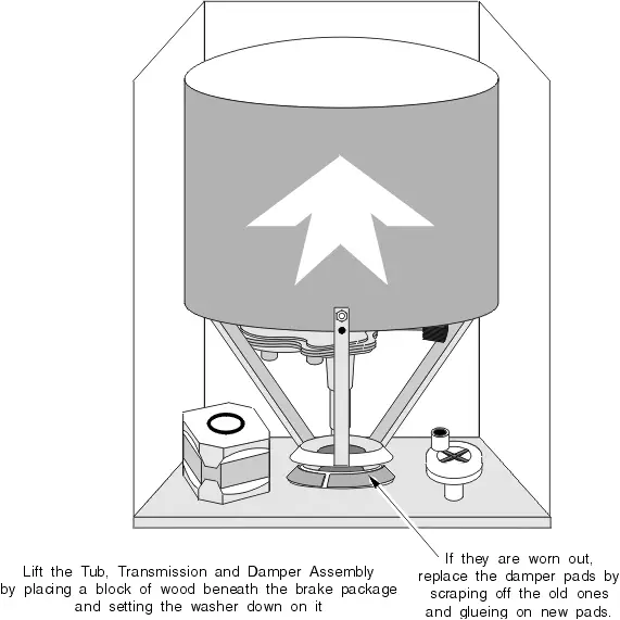
Lean the washer back against the wall at an angle. Place a 4x4 wood block directly underneath the transmission pulley and lower the machine onto the wood block. This will lift the tub, transmission and damper assembly several inches. (Figure M-16)
If the old damper pads are just dry and not too worn, lubricate them with a silicone-based grease, available from your appliance parts dealer.
If the old damper pads look too worn, scrape them off and replace them. Get a damper pad kit from your appliance parts dealer. It should include the glue you need. Use rubbing alcohol to clean and prepare the surface to be glued.
Please share our .