Dishwasher Electrical Problems
Many household handymen will tackle just about any job, but are downright scared of electricity. It's true that you have to be extra careful around live circuits due to the danger of getting shocked. But there's no mystery or voodoo about what we'll be doing. I'll cut out most of the electric theory for you. If you're one of those folks who's a bit timid around electricity, all I can say is read on, and don't be too nervous. It will come to you.
Nowadays, dishwashers are being made as efficient as possible, due in no small part to government energy efficiency requirements. Heating water can use a lot of energy, so designers are mimimizing water usage and heater operation. The trick is in achieving a balance; that is, keeping enough hot, clean water in the tub to clean the dishes, while minimizing energy and water usage.
In practical terms, this translates to trying to measure the water temp, and also how dirty the water is, using things like thermistors and turbidity sensors.
Designers use microprocessors (basically computers, on solid state circuit boards) to adapt the functions of the dishwasher to current wash conditions. However, the computer needs some kind of input in order to make decisions.
THERMISTORS
Unlike thermostats, a thermistor is not just a switch. It is actually a resistor whose resistance varies with the temperature it senses. Resistance is a signal that a microprocessor can use to make decisions, like when and how long to turn on the water heater. Thus the thermistor essentially translates temperature into an electrical signal that the microprocessor can understand.
TURBIDITY SENSORS
If the dishwasher is loaded with a lot of food residue, it will need extra rinse cycles to assure that the dishes come out clean. "Turbidity sensors" measure how dirty the water is, so the microprocessor can adjust the number of rinse cycles.
TRICKS OF THE TRADE
Wanna know a secret? For professionals, an awful lot of diagnosis is done by guessing; ESPECIALLY with electronic components. It's just simply much faster and easier to change out a circuit board and see if the machine works, than it is to try to figure out what component of that board has failed.
Unfortunately, circuit boards are not cheap. And being electrical parts, they are usually not returnable. Meaning that if you didn't guess correctly, you just ate a hundred-dollar circuit board, and your machine still has the same problem that needs fixing.
If you're a professional technician, that's not a problem. You can just yank the circuit board back out. and use it on the next one of these machines that you see.
However, if you're a DIY'er, it's a BIG problem. You have no interest in owning a hundred-dollar circuit board that you don't need, and can't return.
So I know this will be controversial, and you will SELDOM hear me say this, but my PRACTICAL advice is this: if you have a problem that you think you've traced to the electronic controls in a machine, call a professional service technician to fix it. Since they can get a volume discount on the part, it will PROBABLY end up costing you not much more than trying to do it yourself.
Sometimes you need to read a wiring diagram, to make sure you are not forgetting to check something. Sometimes you just need to find out what color wire to look for to test a component. It is ESPECIALLY important in diagnosing a bad timer.
Usually your wiring diagram is either pasted to the inside of the door panel, or else contained in a plastic pouch inside the door itself. Either way, you must remove the door panel to get to it as described in section 5-2.
If you already know how to read a wiring diagram, you can skip this section.
Each component should be labelled clearly on your diagram. Look at figure 6-A. The symbols used to represent each component are pretty universal.
Wire colors are abbreviated and shown next to each wire. For example, Y means a yellow wire, V means Violet, R means red, LBU means light blue. Black is usually abbreviated BK, blue is usually BU. GR or GN are green, GY is gray. A wire color with a dash or a slash means --- with a --- stripe. For example BU-W means Blue with a white stripe, T/R means tan with a red stripe.

A few notes about reading a wiring diagram:
Notice that in some parts of the diagram, the lines are thicker than in other parts. The wiring and switches that are shown as thick lines are inside of the timer.
The small white circles all over the diagram are terminals. These are places where you can disconnect the wire from the component for testing purposes. The small black circles indicate places where one wire is connected to the other. If two wires cross on the diagram without a black dot where they cross, they are not connected.
If you see dotted or shaded lines around a group of wires, this is a switch assembly; for example, a pushbutton selector switch assembly or a relay. It may also be the timer, but whatever it is, it should be clearly marked on the diagram. Any wiring enclosed by a shaded or dotted box is internal to a switch assembly and must be tested as described in section 6-3(a) or (b).
Switches may be numbered or lettered. Usually the terminals on the outside of the timer are stamped or printed with the color of the wire that is supposed to attach to it.
To test a switch with a certain marking, mark and disconnect all the wires. Connect your ohmmeter to the two terminal leads of the switch you want to test. For example, in figure 6-B, if you want to test the door switch, take power off the machine, disconnect the black and tan wires from it and connect one test lead each terminal. Then flick the switch back and forth. It should close and open. If it does, you know that contact inside the switch is good.

Remember that for something to be energized, it must make a complete electrical circuit. You must be able to trace the path that the electricity will take, FROM the wall outlet backTO the wall outlet. This includes not only the component that you suspect, but all switches leading to it, and sometimes other components, too.
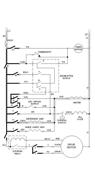
In Figure 6-B, which shows a typical electric dishwasher, L1, L2, are the main power leads; they go directly to your wall plug. Between L1 and L2, you will see 110 volts.
Let's say you need to check out why the detergent dispenser is not working.
Following the gray-shaded circuit in figure 6-B, note that the electricity "flows" from L1 to L2.
From L1 the electricity flows to the door switch. The power then goes through a tan wire to the timer. Then it goes through switch number 15, then number 11. These switches are located inside of the timer (you know this because they are drawn with thick lines.) They must be closed.
The electricity then flows through an orange and black wire (O-BK) to the detergent dispenser bimetal. The bimetal is a kind of resistor (the zig-zag lines tell you this.)
Then the electricity flows through a white and red wire to the heater. So if the heater is burnt out, the detergent dispenser won't work. Hmmmm........ interesting, huh?
Electricity then flows back to the wall plug, L2, through a white wire.
TESTING THE CIRCUIT
To test for the break in the circuit, simply isolate each part of the system (remove the wires from the terminals) and test for continuity. For example, to test the bimetal in our example, pull the wires off each end and test continuity across the terminals as described in section 6-3(f).
Switches 15 and 11 are shown in bold lines, so they are inside the timer. For now, let's ignore them. (The timer is the last thing you should check; see section 6-3(b).
Since a burnt out bimetal element is the most likely cause of this symptom, first test the bimetal for continuity. If you have good continuity, something else in the circuit must be defective. The heater, for example. Test it the same way.
If NONE of the other components appear to be defective, test the timer as described in section 6-3(b).
To check for a wire break, you would pull each end of a wire off the component and test for continuity through the wire. You may need to use jumpers to extend or even bypass the wire; for example, if one end of the wire is in the control console and the other end in underneath the machine. If there is no continuity, there is a break in the wire! It will then be up to you to figure out exactly where that break is—there is no magic way. If you have a broken wire, look along the length of the wire for pinching or chafing. If there is a place where the wires move , check there first. Even if the insulation is O.K., the wire may be broken inside.
Sometimes you can eliminate possibilities just simply be studying the wiring diagram for a few minutes. For example, let's say your timer is not advancing during any cycle. Following the gray line in figure 6-C, the timer is fed through three different circuits. Sometimes it gets its power through timer switch 22, sometimes it gets power from switch "D" inside the pushbutton selector switch, and it can also get power from the thermostat. It is unlikely that all three switches are bad, so the likelihood is that the timer motor itself is on the fritz.

Most components are tested simply by removing power and placing a resistance meter across them. However some need to be tested with a volt meter while energized. Occasionally, if the component is inexpensive enough, it's easier to just replace it and see if that solves the problem.
Testing switches and solenoids is pretty straightforward. Take all wires off the component and test resistance across it as described in section 2-5(b).
Switches should show good continuity when closed and no continuity when open.
Solenoids should show SOME resistance, but continuity should be good. If a solenoid shows no continuity, there's a broken wire somewhere in the coil. If it shows no resistance at all, it's shorted.
THERMOSTATS
A thermostat is just a switch that opens and closes according to temperature changes that it senses. They can be difficult to test. However, most are usually inexpensive. So if you think you have a bad one, just replace it.
SELECTOR SWITCHBLOCKS
A selector switch block, located in the control panel, is a group of switches all molded into one housing. In your dishwasher, a switchblock will be used to allow you to choose between "normal wash" and "pots and pans" for example, or a "water heat" or "air-dry" option. When you select an option, "normal wash," for example, you are de-selecting the other options, for example "pots and pans." This is the main function of the switchblock.
Testing switch blocks is much like testing timers. You must look at the wiring diagram to see which of the terminals will be connected when the internal switches are closed.
Keep in mind, however, that you must also know which of the internal switches close when an external button is pressed. When you press one button on the switchblock, several of the switches inside may close at once. To test a switchblock, in addition to the wiring diagram, you must have a chart that gives you this info. Usually this is attached to the wiring diagram or to the timer sequencing chart.
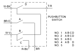
Using the diagram and chart in figure 6-D, lets say we want to test switch "A." We see that with button number 1 pressed, only switches "A" and "D" inside the switchblock are closed. With button number 5 pressed, switches "B" and "D" are closed, and "A" is open. The two wires that connect to switch "A" are the BR-O (brown wire with an orange stripe) and the BR (brown) wire. Remove those two wires and put a resistance meter across those two terminals. Then push buttons 1 and 5 alternately, to see if the switch opens and closes.
Test other switches similarly. Figure out when they're closed, when they're open, and test resistance while operating the switch.
If the switchblock is bad, replace it.
The timer is the brain of the dishwasher. It controls everything in the cycle. In addition to telling the motor when to run, it may also activate the heating circuit or heating control circuits, fill valve, detergent dispensers, motor direction or drain valve solenoid, etc.
Most timers are nothing more than a motor that drives a set of cams which open and close switches. Yet it is one of the most expensive parts in your dishwasher, so don't be too quick to diagnose it as the problem.
Usually the FIRST thing a layman looks at is the timer; it should be the LAST. And don't forget that timers are electrical parts, which are usually non-returnable. If you buy one, and it turns out not to be the problem, you've just wasted the money.
Solid state timers are difficult and expensive to diagnose. If you suspect a timer problem in a solid-state system, you can try replacing it, but remember that it's expensive and usually non-returnable (being an electrical part.) If you have one of these units that's defective, you can check into the cost of replacing it, but it's been my experience that you usually will end up just replacing the whole dishwasher or calling a technician. If you do call a technician, make sure you ask up front whether they work on solid-state controls.
TIMER DIAGNOSIS
If the timer drive motor is not advancing only in certain cycles, there may be a switch or thermostat that feeds it that is bad. See the example in section 6-1 and figure 6-C.
If the timer is not advancing in all cycles, well, that's pretty obvious. Replace the timer or timer drive motor, or have it rebuilt as described below.
Timers can be difficult to diagnose. The easiest way is to go through everything else in the system that's malfunctioning. If none of the other components are bad, then it may be the timer.
Remember that a timer is simply a set of on-off switches. The switches are turned off and on by a cam, which is driven by the timer motor. Timer wires are color-coded or number-coded.
Let's say you've got a detergent dispenser problem. Following the shaded circuit in figure 6-E, you test the door switch, detergent dispenser and heater. They all test OK. So you think you've traced the problem to your timer.
First take power off the machine or unplug it. Looking at your wiring diagram, you see that the circuit goes through the tan wire entering the timer, and the O-BK wire leaving it. There is also a W-V terminal that you can use to test the switches separately. Remove those wires from the timer. Touch the resistance meter test leads to terminals T and W-V.
Make sure the timer is in the "on" position and slowly turn the timer all the way through a full cycle.
You should see continuity make and break at least once in the cycle; usually several times. If it doesn't, the internal contacts are bad; replace the timer. Repeat the process with the test leads between the W-V and the O-BK terminals.
You can drive yourself crazy trying to figure out just exactly when during the cycle the switch is supposed to open and close. Leave that to the design engineers. Just satisfy yourself that the switch is, indeed, opening and closing at some time during the cycle.
In general, timers cannot be rebuilt by the novice. Check with your parts dealer; if it can be rebuilt, he'll get it done for you. If it's a common one, your parts dealer may even have a rebuilt one in stock.
For the most part, if your timer is acting up, you need to replace it. To replace, mark the wires or note the color codes written on the timer. If you need to, you can draw a picture of the terminal arrangement and wire colors. If possible, change over the timer wires one-by-one—it can be easier. If there are any special wiring changes, they will be explained in instructions that come with the new timer.
A motor that is trying to start, but can't for whatever reason, is using one heck of a lot of electricity. If you think about it, essentially the motor is as overloaded as it can be. So much, in fact, that if it is allowed to continue being energized without the shaft turning, it will start burning wires. To prevent this, an overload switch is installed on motors to cut power to them if they don't start within a certain amount of time.
If the motor is trying to start, but can't, you will hear certain things. First will be a click, followed immediately by a buzzing sound. Then, after about 5 to 20 seconds of buzzing, another click and the buzzing will stop. The sounds will keep repeating every minute or two. This is the motor cutting in and out on the overload switch. In some extreme cases, you may even smell burning.
If you hear the motor doing this, but it won't start, disconnect power and disassemble or remove the pump as described in Chapter 5. Check for anything that might be jamming the pump. If so, remove it and you are probably back in business.
See if the pump shaft turns easily by hand. If it feels sticky or gritty, the bearings are probably bad.
Try testing for resistance across the motor windings. In most machines, the white motor lead is common. One at a time, test for resistance between the white lead and the other two or three leads as described in section 2-5(b). There should be some resistance. No resistance or no continuity at all indicates a bad motor. Also touch the test leads between each motor lead and the motor cage, or frame. Except for the green lead, there should be no continuity. If there is continuity, replace the motor. Continuity between the green motor lead and the motor cage is fine; the green wire is the ground wire.
If you're not sure how to test the motor, take it to your parts dealer or to an electric motor shop. Have them test the motor.
If it won't even start without a load on it, the motor is bad. If you have an ammeter, the stalled motor will be drawing 10 to 20 amps or more. Replace it.
NOTE: When replacing the motor, always use a new relay! They are a matched pair!
STARTING RELAY
Motors use a lot of electricity compared to other electrical components. The switches that control them have to be built bigger than other kinds of switches, with more capacity to carry more electricity.
The switches involved in running an electric motor are too big to conveniently put inside the control console or timer. Besides that, there are safety considerations involved in having you touch a switch that carries that much electricity directly, with your finger.
The way they solve that problem is to make a secondary switch. A big switch that starts the motor, which is closed by the little switch inside the timer or one you push with your finger. A relay.
When you first start a motor, it draws even more power than when it is running. So you need to close a really big switch to start the motor, then open it back up once the motor gets up to speed.
A starting relay is simply an electromagnet that closes the bigger switch. When the motor starts, the electromagnet stops, and the "start" circuit stops. But the "run" circuit stays on, and the motor runs.
Dishwashers have a relay starting switch mounted either beneath the tub or in the control console.
You can usually figure out which terminals to test across by looking at the wiring diagram. If you're not sure how, take the switch to your parts dealer. They can usually help you test the switch. If not, just replace it. They're not too expensive.
If the motor is stalled (buzzing and/or tripping out on the overload switch) and the starting switch tests O.K., the motor is bad. Replace it.
Electric heater elements are tested by measuring continuity across them as described in section 2-5(b). A good heater will show continuity, but quite a bit of resistance. A bad heater will usually show no continuity at all.
There is a junction box in either the left front or right front corner of the machine, beneath the kickplate. (See figure 5-C in Chapter 5. The main power leads are attached to the dishwasher inside this box, usually with wire nuts. This connection is subject to vibration and occasionally moisture, and should be considered suspect if the machine isn't getting any power.
With one exception, door dispensers are triggered by either a solenoid, a wax motor, or a bimetal. This trigger touches the spring-loaded dispenser and mechanically pops it open. To test them, remove the wire leads and test resistance across the terminals as described in section 2-5(b).
The exception is GE or Hotpoint machines, in which the dispenser is mechanically tripped by a cam on the timer.
A wax motor is neither a motor, nor does it contain any wak. It is essentially a bimetal with a housing and a plunger, and is tested in the same way as a bimetal - by testing resistance across it.
Most solenoids are 110 volt. BIMETALS ARE NOT!!! Do NOT put 110 volts across bimetal triggers to test them—you will burn them out. ONLY test them with a resistance meter. They are actually just a form of resistor, so you should see some resistance. If they are fried, you will usually see no continuity at all. Replace the part.
The voltage is cut is by putting the bimetal in series with another component, usually the heater. "In series" means that the electricity must go through both the heater and the bimetal to complete the circuit. When two components are in series, they "share" the full voltage. The higher the resistance, relative to the other component, the more voltage it will "steal" from the other component. Since the resistance of the heater is very high compared to the resistance of the bimetal, the heater takes most of the voltage, and the bimetal is left with only a few volts.
Note that certain Kitchenaid and Thermador dishwashers use a similar, but different system. Many of these machines used a solenoid to open the detergent dispenser, but some used a bimetal. On those that used a bimetal, the bimetal is wired in series with the drive motor, and the opening of the detergent dispenser depends on how much current the motor is using. How much current the motor is using depends on the load on the motor. If the load on the motor is too low, it will not draw enough current, and the bimetal will not trigger the dispenser open, even if the bimetal is in good condition.
What will cause a low load on the motor? Low water level. So in Kitchenaid and Thermador machines with bimetal triggers, a low water level will cause the detergent dispenser not to open!
If the door dispenser in these dishwashers is not opening, check the water inlet valve for proper operation. Specifically, check that the inlet strainer screen is clear, and if the valve has been replaced recently, make sure you got the right valve, with the right flow control washer. (See section 6-3(h).

If your machine uses a blower to dry the dishes, it is located beneath the tub, usually on the right side of the machine. To test, unplug the machine and remove the two motor leads. Test for continuity as described in section 2-5(b). No continuity indicates a break in the winding. There should be some resistance.
Also touch the test leads between each motor lead and the motor cage, or frame. There should be no continuity. If there is, replace the dishwasher motor.
The water fill valve (also the drain valve, on older Kitchenaid dishwasher machines) is solenoid operated. Test them for continuity as described in section 2-5(b) and replace if defective.
When replacing the fill valve, use an O.E.M. part, or at least make sure the flow control washer is the same as in the original machine. Aftermarket parts may have a different flow control washer, which can cause high or low waterfill in your dishwasher machine.
Please share our .