Refrigerator Repair & Icemaker Repair
DON'T use them on refrigerators. "Green" plugs usually work fine on resistive loads such as heaters and incandescent lights. But in my opinion, you should not use them on electronics, and things that are motorized. These things are made to operate on electricity with certain "waveform" characteristics. A "green" plug modifies those characteristics; you are asking for trouble.
Refrigerators have SEVERAL motors in them, and modern refrigerators have electronic components, too. Green plugs have caused all kinds of problems in fridges, such as moisture buildup due to slower fan speeds, and compressor starting and heating problems.
Equally importantly, a 'green" plug might VOID THE WARRANTY on your fridge.
Because of government-mandated efficiency requirements, modern refrigerators already have a great energy-saving features built into them. You don't need a green plug on a fridge...don't use them!
Find yourself a good appliance parts dealer. You can find them in the Yellow Pages under the following headings:
- APPLIANCES, HOUSEHOLD, MAJOR
- APPLIANCES, PARTS AND SUPPLIES
- REFRIGERATORS, DOMESTIC
- APPLIANCES, HOUSEHOLD, REPAIR AND SERVICE
Call a few of them and ask if they are a repair service, or if they sell parts, or both. Ask them if they offer free advice with the parts they sell. (Occasionally, stores that offer both parts and service will not want to give you advice.) Often, the parts counter men are ex-technicians who got tired of the pressures of going into stressed-out peoples' houses and fixing appliances. They can be your best friends; however, you don't want to badger them with TOO many questions, so know your basics before you start asking questions.
Some parts houses may offer service too. Be careful! They may try to talk you out of even trying to fix your own refrigerator. They'll tell you it's too complicated, then in the same breath, "guide" you to their service department. Who are you gonna believe, me or them? Not all service/parts places are this way, however. If they genuinely try to help you fix it yourself and you find that you can't fix the problem, they may be a really good place to look for service. Think about it?if they sold you this book, then they're genuinely interested in helping do-it-yourselfers!
When you go into the store, have ready your make, model and serial number from the nameplate of the fridge (not from some sticker inside the fridge). If there is a B/M number on the nameplate, have that with you, too.
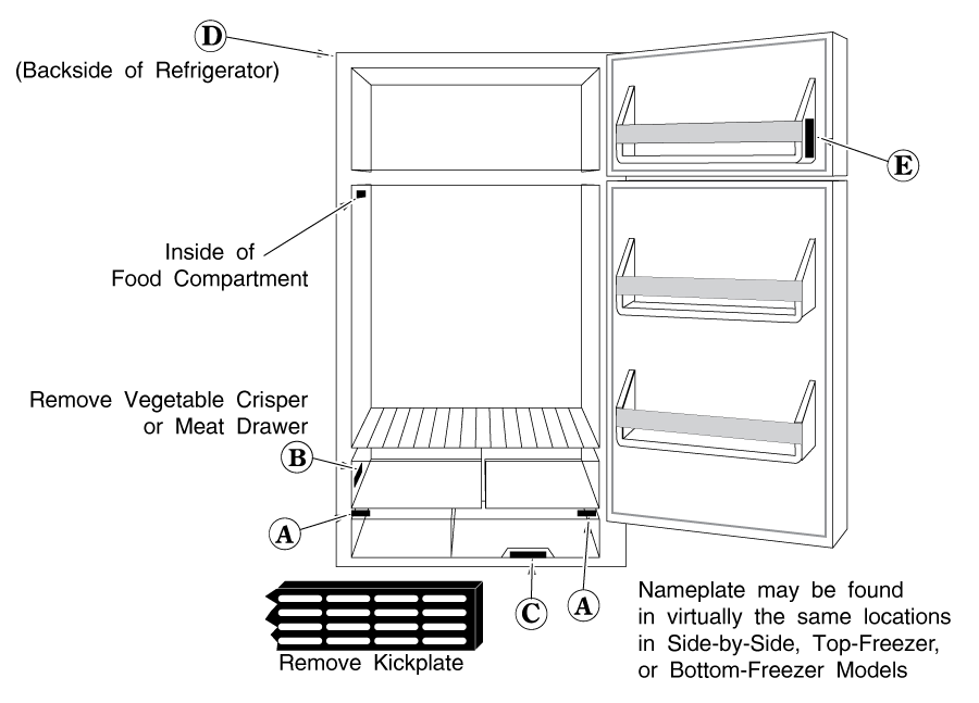
NAMEPLATE INFORMATION
The metal nameplate information is usually found in one of the places shown in Figure 1:
A) Along the bottom panel; left, right or anywhere in-between.
B) Inside the fridge or freezer section, near the bottom. You may have to remove a crisper drawer to see it.
C) Remove the kickplate and look along the condenser air openings.
D) Somewhere on the back of the refrigerator, usually very high or very low, or possibly on any wiring diagram that may be pasted to the back of the refrigerator.
E) If you absolutely cannot find a metal nameplate, some refrigerators have a paper sales sticker left on, just inside the door. This will be an incomplete model number, but it is better than nothing and it should be good enough to get most parts with.
If all else fails, check the original papers that came with your fridge when it was new. They should contain the model number SOMEWHERE.
If you have absolutely NO information about the fridge anywhere, make sure you bring your old part to the parts store with you. Sometimes they can match an old part by looks or by part number.
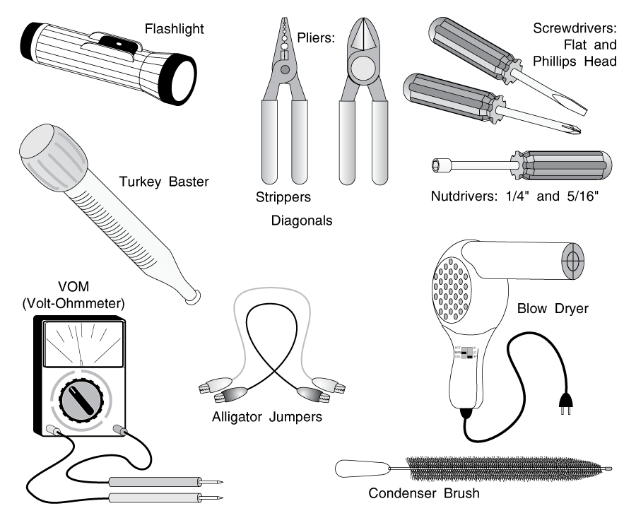
The tools that you will probably need are listed below. Some are optional. The reason for the option is explained.
SCREWDRIVERS: Both flat and phillips head; two or three different sizes of each. It is best to have at least a stubby, 4″ and 6″ sizes.
NUTDRIVERS: You will need at least a 1/4″ and a 5/16″ nut driver. 4 or 6″ ones should suffice, but it's better to have stubbies, too.
BLOW DRYER and SYRINGE TYPE TURKEY BASTER: For manually melting frost and ice.
ALLIGATOR JUMPERS (sometimes called a "CHEATER" or "CHEATER WIRE"): small gauge (14-16 gauge or so) and about 12 to 18 inches long; for testing electrical circuits. Available at your local electronics store. Cost: a few bucks for 4 or 5 of them.
ELECTRICAL PLIERS or STRIPPERS and DIAGONAL CUTTING PLIERS: For cutting and stripping small electrical wire.
BUTT CONNECTORS, CRIMPERS, WIRE NUTS AND ELECTRICAL TAPE: For splicing small wire.
FLASHLIGHT: For obvious reasons.
VOM(VOLT-OHM METER): For testing circuits. If you do not have one, get one. An inexpensive one will suffice, as long as it has both "A.C. Voltage" and "Resistance" (i.e. R x 1, R x 10, etc.) settings on the dial. It will do for our purposes. If you are inexperienced in using one, get an analog (pointer) type (as opposed to a digital.)
CONDENSER BRUSH: For cleaning out that dusty "black hole" beneath your fridge, otherwise known as your condenser. It is a long, stiff-bristled brush especially made for knocking out massive wads of dust from your condenser grille. I have seen jury-rigged bottle brushes and vacuums used, neither of which clean sufficiently. C'mon?buy the right tool for the job. They're cheap enough.
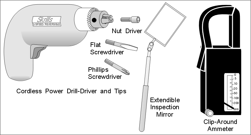
SNAP-AROUND AMMETER: For determining if electrical components are energized. Quite useful; but a bit expensive, and there are alternative methods. If you have one, use it; otherwise, don't bother getting one.
EXTENDIBLE INSPECTION MIRROR: For seeing difficult places beneath the refrigerator and behind panels.
CORDLESS POWER SCREWDRIVER OR DRILL/DRIVER WITH MAGNETIC SCREWDRIVER AND NUTDRIVER TIPS: For pulling off panels held in place by many screws. It can save you lots of time and hassle.
Many home handymen are very intimidated by electricity. It's true that diagnosing and repairing electrical circuits requires a bit more care than most operations, due to the danger of getting shocked. But there is no mystery or voodoo about the things we'll be doing. Remember the rule in section 3-4 (1); while you are working on a circuit, energize the circuit only long enough to perform whatever test you're performing, then take the power back off it to perform the repair. You need not be concerned with any theory, like what an ohm is, or what a volt is. You will only need to be able to set the VOM onto the right scale, touch the test leads to the right place and read the meter.
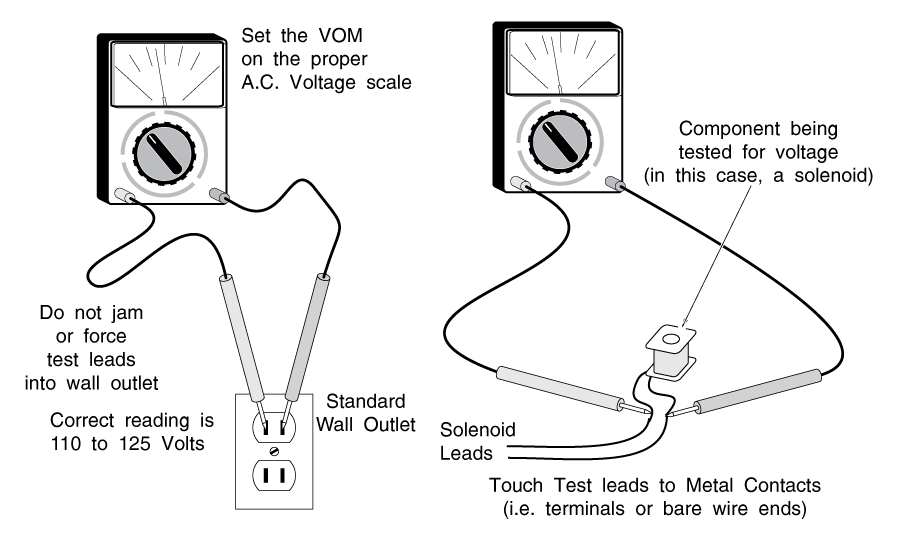
In using the VOM (Volt-Ohm Meter) for our purposes, the two test leads are always plugged into the "+" and "-" holes on the VOM. (Some VOMs have more than two holes.)
Set the VOM's dial on the lowest VAC scale (A.C. Voltage) that's over 120 volts. For example, if there's a 50 setting and a 250 setting on the VAC dial, use the 250 scale, because 250 is the lowest setting over 120 volts.
Touch the two test leads to the two metal contacts of a live power source, like a wall outlet or the terminals of the motor that you're testing for voltage. (Do not jam the test leads into a wall outlet!) If you are getting power through the VOM, the meter will jump up and steady on a reading. You may have to convert the scale in your head. For example, if you're using the 250 volt dial setting and the meter has a "25" scale, simply divide by 10; 120 volts would be "12" on the meter.
Don't let the word "continuity" scare you. It's derived from the word "continuous." In an electrical circuit, electricity has to flow from a power source back to that power source. If there is any break in the circuit, it is not continuous, and it has no continuity. "Good" continuity means that there is no break in the circuit.
For example, if you were testing a heater element to see if it was burned out, you would try putting a small amount of power through the heater. If the heater element was burned out, there would be a break in the circuit, the electricity wouldn't flow, and your meter would show no continuity.
That is what the resistance part of your VOM does; it provides a small electrical current (using batteries within the VOM) and measures how fast the current is flowing. The current flow is measured in Ohms; the more resistance that there is to current flow, the more Ohms your meter will read.
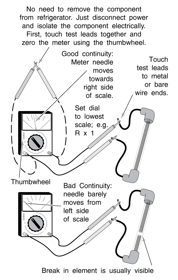
To use your VOM to test continuity, set the dial on (resistance) R x 1, R x 10, or whatever the lowest setting is. Touch the metal parts of the test leads together and read the meter. It should peg the meter all the way on the right side of the scale, towards "0" on the meter's "resistance" scale. If the meter does not read zero resistance, adjust the thumbwheel on the front of the VOM until it does read zero. If you cannot get the meter to read zero, the battery in the VOM is low; replace it.
If you are testing, say, a heater, first make sure that the heater leads are not connected to anything, especially a power source. If the heater's leads are still connected to something, you may get a reading through that something. If there is still live power on the item you're testing for continuity, you will burn out your VOM in microseconds and possibly shock yourself.
Touch the two test leads to the two bare wire ends or terminals of the heater. You can touch the ends of the wires and test leads with your hands if necessary to get better contact. The voltage that the VOM batteries put out is very low, and you will not be shocked. If there is NO continuity, the meter won't move. If there is GOOD continuity, the meter will move toward the right side of the scale
and steady on a reading. This is the resistance reading. Most of the time this doesn't concern us; we only care that we show good continuity. If the meter moves only very little and stays towards the left side of the scale, that's BAD continuity; the heater is no good. In a glass-tube or bare-element heater, you may be able to see the physical break in the heater element, just like you can in some light bulbs.
If you are testing a switch or a thermostat, you will show little or no resistance (good continuity) when the switch or thermostat is closed, and NO continuity when the switch is open. If you do not, the switch is bad.
Ammeters are a little bit more complex to explain without going into a lot of electrical theory. If you own an ammeter, you probably already know how to use it.
If you don't, don't get one. Ammeters are expensive. And for our purposes, there are other ways to determine what an ammeter tests for. If you don't own one, skip this section.
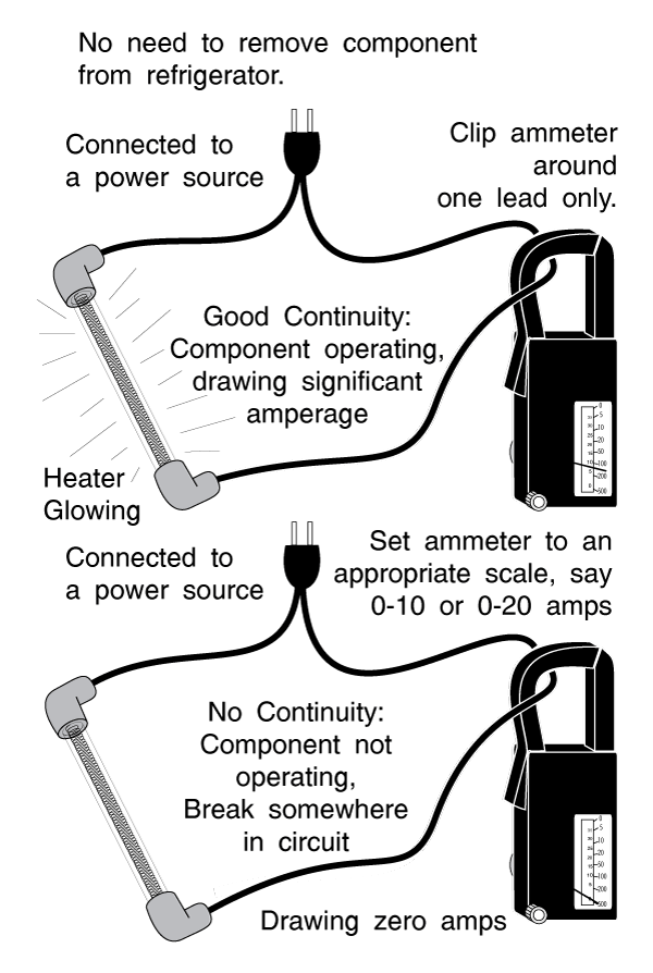
For our purposes, ammeters are simply a way of testing for continuity without having to cut into the system or to disconnect power from whatever it is we're testing.
Ammeters measure the current in amps flowing through a wire. The greater the current that's flowing through a wire, the greater the magnetic field it produces around the wire. The ammeter simply measures this magnetic field, and thus the amount of current, flowing through
the wire. To determine continuity, for our purposes, we can simply isolate the component that we're testing (so we do not accidentally measure the current going through any other components) and see if there's any current flow.
To use your ammeter, first make sure that it's on an appropriate scale (0 to 10 or 20 amps will do). Isolate a wire leading directly to the component you're testing. Put the ammeter loop around that wire and read the meter. (Figure 6)
What if that you have trouble finding the wire lead to, say, a defrost heater that you're testing, because the wires are frozen into a block of ice?
If you isolate all systems so the heater is the only thing energized, then you can test the easily accessible main power cord for current, and it must be the current being used by the heater.
This is relatively easy to do. Turn the "energy saver" switch to the "economy" position to shut off the anti-sweat mullion heaters (See section 4-1.) Close the refrigerator door to make sure the lights are off. Set the defrost timer to the defrost mode. This will stop the compressor, and energize the defrost heater (if it is working; that, of course, is what we're testing.) Remove the lower back
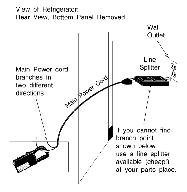
panel of the fridge and find where the main power cord branches off in two directions. (See Figure 7) Test one lead (one lead only) for current flow. There may still be a tiny mullion heater energized in the butter conditioner or on the defrost drain pan, but the current that these heaters draw is negligible for our purposes (less than an amp). If you have any substantial current flow, it's got to be through the defrost heater. If you don't, the defrost heater or terminating thermostat is probably defective.
1) Always de-energize (pull the plug or trip the breaker on) any refrigerator that you're disassembling. If you need to re-energize the refrigerator to perform a test, make sure any bare wires or terminals are taped or insulated. Energize the unit only long enough to perform whatever test you're performing, then disconnect the power again.
2) NEVER EVER chip or dig out ice from around the evaporator with a sharp instrument or knife. You WILL PROBABLY puncture the evaporator and you WILL PROBABLY end up buying a new refrigerator. Use hot water and/or a blow dryer to melt ice. If you use a blow dryer, take care not to get water in it and shock yourself.
Better yet, if you have the time and patience, leave the fridge open for a few hours and let the ice melt naturally. You can remove large, loose chunks of ice in the evaporator compartment by hand, but make sure there aren't any electrical wires frozen into the chunks of ice before you start pulling them.
3) Always re-install any removed duck seal, heat shields, styrofoam insulation, or panels that you remove to access anything. They're there for a reason.
4) You may need to empty your fridge or freezer for an operation. If you do not have another fridge (or a friend with one) to keep your food in, you can generally get by with an ice chest or a cardboard box insulated with towels for a short time. Never re-freeze meats; if they've already thawed, cook them and use them later.
5) If this manual advocates replacing a part, REPLACE IT!! You might find, say, a fan motor that has stopped for no apparent reason. Sometimes you can flip it with your finger and get it going again. The key words here are apparent reason. There is a reason that it stopped?you can bet on it?and if you get it going and re-install it, you are running a very high risk that it will stop again. If that happens, you will have to start repairing your refrigerator all over again. There may be a hard spot in the bearings; or it may only act up when it is hot, or cold...there are a hundred different "what if's." Very few, if any, of the parts mentioned in this book will cost you over ten or twenty dollars. Don't be penny-wise and dollar-dumb. Replace the part.
6) Refrigerator defrost problems may take a week or more to reappear if you don't fix the problem the first time. That's how long it will take the evaporator to build up enough frost to block the airflow again. After fixing a defrost problem, keep an eye out for signs of a recurrence for at least a week. The sooner you catch it, the less ice you'll have to melt.
7) You may stop the compressor from running using the defrost timer or cold control, by cutting off the power to the fridge, or simply by pulling the plug out of the wall. However, if you try to restart it within a few minutes, it may not start; you may hear buzzing and clicking noises. (See section 5-3(e)). If the system has not had enough time for the pressure within to equalize, there will be too much back pressure in the system for the compressor motor to overcome when trying to start. This is nothing to be alarmed about. Simply remove the power from the compressor for a few more minutes until the compressor will restart.
8) Do not lubricate any of the timers or motors mentioned in this manual. They are permanently self-lubricated. In a cold environment, oil will become more viscous and increase friction, rather than decrease it. If you have a sticky fan motor or timer, replace it.
Please share our .